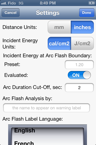
Arc Flash Analytic app for iPhone and iPad
Developer: ARCAD INC.
First release : 31 Oct 2013
App size: 5.41 Mb
The Arc Flash Analytic software has been developed based on IEEE 1584 Guide for Performing Arc-Flash Hazard Calculations as an easy to use and comprehensive tool for calculating incident energy and arc flash boundary, for determining limited, restricted, prohibited approach boundaries and hazard risk category required by NFPA 70E, NEC / CEC and OSHA when work is to be performed on or near the energized equipment.
The IEEE 1584 empirically derived model was chosen for arc flash analysis due to the models capability to accurately account for a wide variety of setup parameters including:
* open and box equipment configurations
* grounding of all types and ungrounded
* gap between conductors of 3 to 152 mm.
* short circuit currents in the range of 700A to 106kA
* system line voltages in the range of 208V to 15kV
* working distances from 10 to 80 inches
For cases where voltage is over 15kV or gap is outside the range of the model, the theoretically derived Lee method can be applied and it is included in iAFA V1.0
The arc flash software takes equipment configuration, gap between electrodes, grounding type, short circuit fault current value and system voltage on input, and determines arcing fault current at potential point of fault.
For protective devices operating in the steep portion of their time-current curves, a small change in current causes a big change in corresponding operating time. Incident energy is linear with time, and consequently arc current variations may have a big effect on incident energy. The IEEE 1584 proposed solution is to make two arc current and energy calculations: one using the calculated expected arc current and another one using a reduced arc current that is 15% lower.
The arc flash software enables calculations for both of the above considered cases. The iAFA V1.0 arc flash software predicts arcing fault current for a given configuration and amount of the available 3-phase short circuit current. Next, the incident energy, arc flash boundary, shock protection boundaries and level of personnel protective equipment are determined based on equipment configuration, selected upstream protection device ratings and working distance.
Benefits:
* Detailed analysis using the IEEE 1584 equations and the Lee method
* Collect information, take photos of switchgear, MCCs etc. during field walk-downs
* Instantly determine arcing current, incident energy, arc flash, limited, restricted, prohibited approach boundaries, hazard risk category, typical clothing system
* Add fuse and circuit breaker data including time-current characteristics for the devices that are not already featured in the built-in protection device library
* Calculator-style interface makes complex calculations easy to understand
* Provide a safer working environment by specifying the proper level of personal protective equipment. Wearing inadequate clothing is dangerous for obvious reasons, but wearing too much clothing is dangerous due to limited mobility and visibility
* Design safer power systems while insuring compliance with NEC 110.16, OSHA, NFPA 70E, IEEE P1584 and CSA Z462 standards and regulations
* Avoid potential fines, lost productivity, and increased insurance and litigation costs
* Set arc duration cut-off in the 2 to 10 second range
* Evaluate Threshold Incident Energy for a Second Degree Burn
* Generate arc flash warning labels in high resolution graphic format
* Create warning labels in English and a variety of international languages
* Save input configurations, equipment image for future reference
* Send extended report including equipment data, calculation results, arc flash label
* Perform analysis using metric, imperial units


